Sediment Transport and Boundary Layer Equipment (STABLE)
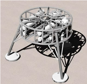
Sediment Transport and Boundary Layer Equipment (STABLE) is a large and complex apparatus designed and built by the National Oceanography Centre’s Mechanical Engineering Group. STABLE III is the third generation of this equipment. which was conceived originally in 1981. It measures the interactions between turbulent currents and sediments at the seabed. It is a tripod standing about 2.5m high and the feet occupy a circle about 3.5m in diameter. It weighs about 2,500kg and cost £250k to design and build.
Before committing to manufacture, an initial three-dimensional Computer Aided Design (CAD) concept-model was subjected to Computational Fluid Dynamics (CFD) analysis. We needed to know if the rig would fall over or move in strong currents and whether the presence of the frame and measuring instruments would interfere unacceptably with the parameters being measured.
The rig is a classic engineering compromise. Many instruments are required to measure the parameters needed for scientific analysis. The batteries and data logging systems need to be held as far above the bed as possible but some of the sensors need to be near the seabed. A large framework is needed to house the instruments but this is directly above the measurement volume between the legs. The legs offer physical protection to some of the sensors. Against this, the apparatus must be small and light enough that it can be handled by a small coastal research ship. Sediment re-suspension is caused primarily by vertical currents and these will be affected directly by the presence of the instrument platform above. The CFD analysis would show us whether the prototype design would perturb measurements to an unacceptable degree.
Working backwards from the wake-effects calculations, the true drag coefficient of the frame was calculated and a better estimate of the toppling current was obtained. As a result, the weight of the STABLE III feet was increased to improve stability in strong currents.
It was also found that the flow varied considerably with height under the frame. In particular, the upper-current meter position was very close to a transition-zone between accelerated and decelerated flows. This indicated that the instrument platform had to be raised to produce less-perturbed flows under the rig.
CFD analysis of reversing flows around the current sensors showed that considerable turbulence was produced by the sensors themselves, their connecting cables and their supports. To reduce this, short, smooth, sausage-shaped shrouds were used to ease the flow round these packages. The shrouds were designed in three-dimensional CAD and the drawings were sent to a supplier, which used computer-controlled machines to produce the rounded fairings. Nowadays, we have the in-house capability to manufacture components like these ourselves.